Welcome, Tuesday, June 9, 2026
Register
Login
Create an IBESMT.com Account
* = Required Field
E-Mail:
*
Invalid Email
* Your E-mail Address will be your username for ibesmt.com
Password:
*
Invalid Password
Password is required.
* Your password must be 8 characters long
Confirm Password:
*
Passwords do not match
Login:
Email:
Password:
Remember Me?:
New User?
Forgot Password?
Login to IBESMT.com to Request a Quote or Participate in a Countdown Sale.
IBESMT.com Forgot Password:
E-mail Address:
Your Password will be sent to your e-mail address from ibe.system@ibesmt.com within a few minutes.
IBESMT.com User Password Reset:
E-mail Address:
Old Password:
*
Old Password is required.
New Password:
*
Invalid Password
New Password is required.
* Your password must be 8 characters long
Confirm New Password:
*
Passwords do not match
800-353-6942
sales@ibesmt.com
All
Machines
Feeders
Spare Parts
Components
Test and Measurement
Search
Toggle navigation
SMT EQUIPMENT
Home
About
Our Facility
Contact
Sell Your Equipment
View All Accessories
SMT Research CP-6 Feeder Cal Jig
Home
->
SMT Accessories
->
SMT Research CP-6 Feeder Cal Jig
SALES STATUS:
Sold
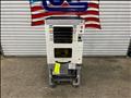
SMT Research CP-6 Feeder Cal Jig
IBE SMT Inventory ID : 100805-001
SMT Research Serial Number :
Vintage :
Details
Includes CP-4 and CP-6 Sub Frames
Includes CP-4 and CP-6 Master Jigs
Specifications ( See Details above for installed options )
Fuji CP-4 and CP-6 Feeder Calibration Jig
Calibration Jig Base- our base allows CP-4, CP-6, and IP/QP BFC style feeders to be calibrated. This is accomplished by interchanging the sub bases. Calibration Jig Base comes equipped with digital micrometers in the X and Y-axis, allowing the user to identify bent feeder bases in the X-axis, and adjust for the Y-axis pickup point (through the eccentric adjuster screw on the feeder).
How to use the feeder calibration system:
Install the sub-base for the style of feeder you are going to calibrate. For CP4/CP6 style feeders you must slide the sub-base forward to the 1st alignment pin, IP/QP style feeders to the 2nd alignment pin, while keeping the sub-base against the guide on the right side. Once the sub-base is in position, tighten the locking screw. Now that you have the sub-base installed, insert the appropriate master gauge onto the sub-base and focus the tool scope. Next, center the crosshairs on the tool scope to the calibration circle on the master gauge using the micrometers. Once the scope is centered to the gauge, then zero by pressing the zero buttons on the X and Y digital micrometers. Remove the master gauge and you are ready to calibrate feeders.
Install appropriate width steel tape into feeder for calibration, then place the feeder on the sub-base. For CP4/CP6 advance feeder by turning the feeder advancement cam clockwise, IP/QP feeders advance by hand all the way forward. Check the image in the tool scope to verify the hole in the steel tape is centered on the crosshairs. If adjustment is needed, loosen the locknut on the eccentric screw and adjust until the calibration mark is centered in the “Y” direction. If the calibration mark is off center in the “X” direction, move the micrometer until the “X” crosshair is lined up and verify that the micrometer does not read more than +/- 0.25mm. The “X” direction corresponds to a bent feeder body and there is no adjustment to fix this problem. Our specification is 0.25mm. Other specifications may be chosen.
Similar Products In Stock
FUJI AIM Tray Tower
IBE ID #:231220-014
FUJI AIM Tray Tower
IBE ID #:231220-015
FUJI NXT Tray Unit
IBE ID #:240816-003
ASYS Laser Marker
IBE ID #:250527-002
Share On:
Share via E-mail
Get Machine Quick Quote
Full Name:
Company Name:
Phone Number:
Email Address:
Pictures
Click Any Image to View Slideshow